

Video Blog 181 - Agilent 34401A Multimeter TFT Conversion
- Details
- Published: Wednesday, 13 May 2026
- Hits: 813
DISCLAIMER: This video is educational only, so if you decide to do the same yourself then you are on your own, I can't be held responsible for any problems/issues/damage/injury that may occur if you decide to follow this blog and try it yourself.
VIDEO BLOG
Off the back of my other TFT upgrades some folks asked for the HP/Agilent/Keysight 34401A, and I just happened to have one that needed a better display since the VFD was quite worn.
Thanks to the person at the following GitHub address that had managed to decode the HP/Agilent/Keysight protocol ot set me on my way:
https://github.com/openscopeproject/HP34401a-OLED-FW/tree/master/src
Download the Pcb Gerbers, Hex file & Instructions/BOM here:
http://www.ianjohnston.com/misc/34401ATFTConversion.zip
The Visual Studio source code is here:
https://github.com/Ian-Johnston/34401A_VS_Display
Notes:
I tested the suspect BluePill board and it looks like it is running the correct clock rates etc:
- SYSCLK = 72 MHz
- HCLK = 72 MHz
- PCLK1 = 36 MHz
- PCLK2 = 72 MHz
- clock source = 8 = PLLCLK
- HSE ready = non-zero
- PLL ready = non-zero
So, there is an alternative hex file in the download which prints the BluePill main loop rate to the TFT on booting the meter - 34401A_VS_Display_with_test.hex
The results speak for themselves, a huge difference in main loop speed:
- Good BluePill = 43596 loops/sec
- Bad BluePill = 849 loops/sec
A result of around 849 strongly suggests fake/clone silicon, flash wait-state problems, bus stalls, bad crystal stability etc.
YouTube Video:
Experiments after the video:
Noise analysis screenshots from WinGPIB:
Agilent 34401A - Unit No.1 - Before copper shield fitted & pin 1 U603 cut
34401A_TFT_1 - TFT conversion, 1.00000VDC Voltage reference, VFD drive electronics still active
34401A_TFT_2 - TFT conversion, VDC mode, grounded inputs via short wire, VFD drive electronics still active
34401A_TFT_3 - TFT conversion, VAC mode, grounded inputs via short wire, VFD drive electronics still active
34401A_TFT_4 - TFT conversion, VAC mode, grounded inputs via 4-way shorting block, VFD drive electronics still active
Agilent 34401A - Unit No.1 - After copper shield fitted & pin 1 U603 cut - (see photos below)
34401A_TFT_9 - TFT conversion, 1.00000VDC Voltage reference, VFD drive electronics still active, shield fitted
34401A_TFT_10 - TFT conversion, VDC mode, grounded inputs via short wire, VFD drive electronics still active, shield fitted
34401A_TFT_11 - TFT conversion, VAC mode, grounded inputs via short wire, VFD drive electronics still active, shield fitted
34401A_TFT_12 - TFT conversion, VAC mode, grounded inputs via 4-way shorting block, VFD drive electronics still active, shield fitted
Agilent 34401A - Unit No.2 - Another 34401A for reference
34401A_VFD_1 - VFD fitted, 1.00000VDC Voltage reference
34401A_VFD_2 - VFD fitted, VDC mode, grounded inputs via short wire
34401A_VFD_3 - VFD fitted, VAC mode, grounded inputs via short wire
34401A_VFD_4 - VFD fitted, VAC mode, grounded inputs via 4-way shorting block
I disabled the VFD driver IC on the display board by cutting the track to pin 1 (Vpp),
the idea being that it might reduce any noise that the VFD switching may have been producing: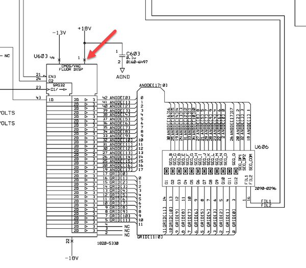
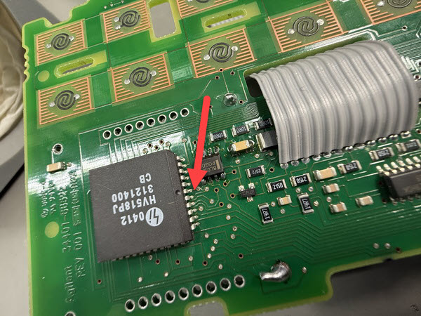
Cut the very short track leading to pin 1 of U603:
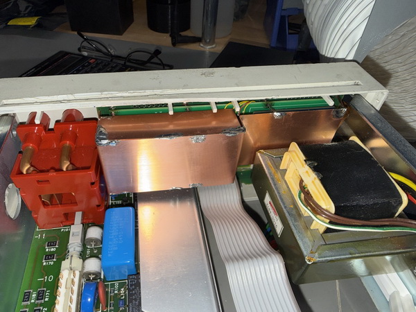
I built a 0.5mm copper shield around the BluePill and TFT driver as an experiment, sorry no drg available,
it's connected to some of the pads on the display board that one of the VFD guard plates was connected to (not power earth):
Programming the BluePill board:
Use an STLink V2 or V3 programmer, clone's should work.
Leave the Boot0 & Boot1 headers as default.
The following can be done with the BluePill in-place and my Pcb connected to the meter,
otherwise you will need +5v power to the BluePill board if doing standalone.
Connect using the SWD connector (the USB connector is not used):
SWDIO -> SWDIO
SWCLK -> SWCLK
GND -> GND
3.3V -> 3.3V (VREF)
NRST -> NRST
Method 1:
Open STM32 ST-LINK Utility
Target -> Connect
File -> Open File
Select .hex file
Target -> Program & Verify
Click Start
Method 2:
Open STM32CubeProgrammer
Select:
ST-LINK
Port = SWD
Click Connect
Open File
Select .hex file
Click Download
