

TFT Conversions Info
- Details
- Published: Sunday, 01 December 2024
- Hits: 2261
DISCLAIMER: This is educational only, so if you decide to do the same yourself then you are on your own, I can't be held responsible for any problems/issues/damage/injury that may occur if you decide to follow this and try it yourself.
TFT Conversions Info
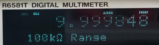
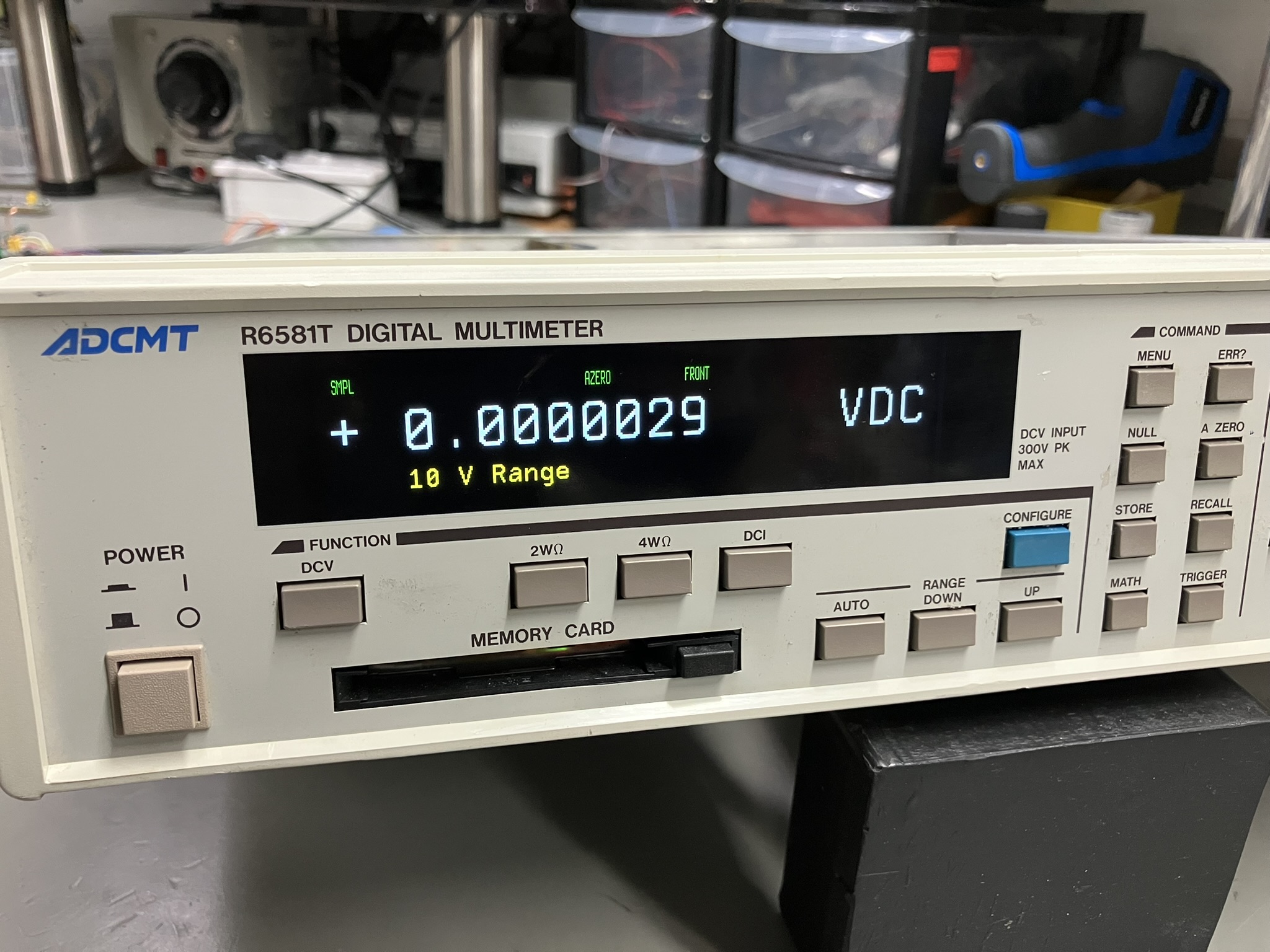
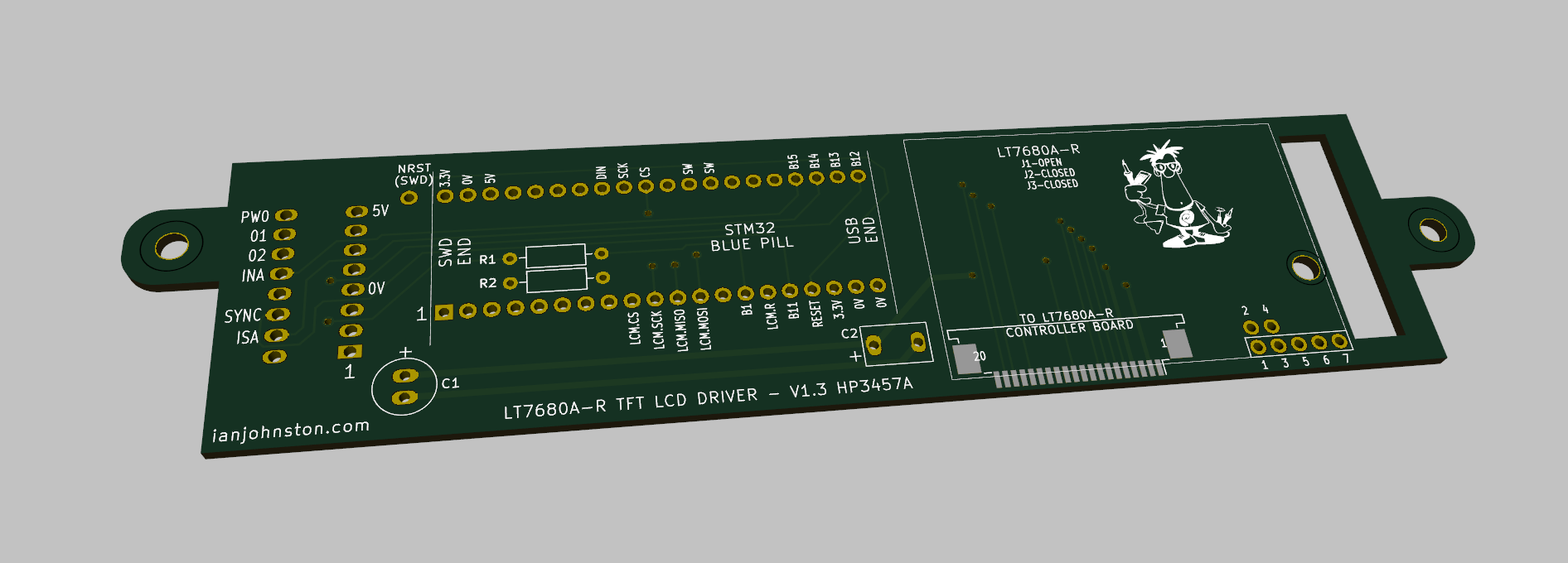
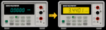
Over the years, I've developed TFT LCD conversions for a variety of electronic test instruments, all based on the same proven hardware and firmware design philosophy. The idea grew from the increasing number of otherwise perfectly serviceable instruments being discarded simply because their original displays had become dim, worn out, or unreadable. Inspired by others who had successfully developed OLED and monochrome LCD/LED replacements, I decided to take the concept a step further and develop full-colour TFT LCD conversions.
This page provides some useful background information for anyone building one of my TFT upgrades, or for those simply interested in what goes on under the hood. If you do build one, I'd love to hear how you got on and see the finished result, so please get in touch.
Hardware
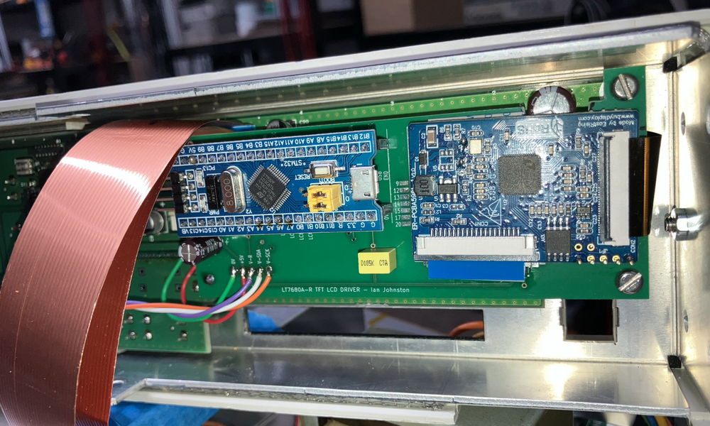
At the heart of each conversion is the inexpensive STM32 "Blue Pill" development board, acting as a bridge between the instrument and a modern TFT LCD.
The firmware monitors the instrument's original display interface, decodes the incoming data stream, and reproduces the display on a high-resolution colour TFT.
There is also a power-up self-test that identifies whether the fitted Blue Pill is a genuine STM32 device or a slower counterfeit clone.
By using the same hardware and software architecture across multiple instruments, new conversions can be developed quickly while maintaining a consistent design and user experience.
Rather than driving the LCD directly, the Blue Pill communicates with an LT7680 graphics controller Pcb over a high-speed SPI interface.
The LT7680A-R IC is a powerful embedded graphics controller with its own display memory, font engine and graphics acceleration, capable of driving high-resolution TFT LCD panels from 320x240 up to 1280x1024 pixels.
By offloading all display generation to the LT7680A-R, the STM32 only needs to send text and graphics commands, leaving the graphics controller to render characters, lines, shapes and images efficiently.
This approach provides smooth display updates, crisp text and a consistent platform that can be reused across many different instrument conversions.
To bring this all together I have designed a PCB that fits the individual instrument and that incorporates a minimal amount of parts to hold the BluePill & LT7680 Pcb, and also to provide the IO connections. It's been designed to be easily assembled by most hobbyists.
The TFT panels themselves are bright, high-contrast IPS displays with excellent viewing angles, offering a significant improvement over the ageing LCDs, VFDs and CRTs found in many vintage instruments, while remaining readily available and inexpensive.
Over the instruments I have converted thus far I have only used two different models of TFT LCD:
https://www.buydisplay.com/bar-type-3-71-inch-240x960-ips-tft-lcd-display-spi-rgb-interface
https://www.buydisplay.com/bar-type-4-58-inch-320x960-ips-tft-lcd-display-spi-rgb-interface
I have a dedicated webpage for each instrument conversion and with it's associated YouTube video. In there you'll also find the Bill of Materials, instructions, Pcb gerbers, mounting bracket info, photos and any other relevant info so you can upgrade your own instrument.
There is also an dedicated Github resource for all my source code including the compiled HEX files for each instrument:
https://github.com/Ian-Johnston?tab=repositories
The individual HEX files are located in the following project sub-folders: /VisualGDB/Debug/
I.E. 34401A_VS_Display.hex
The Development Environment
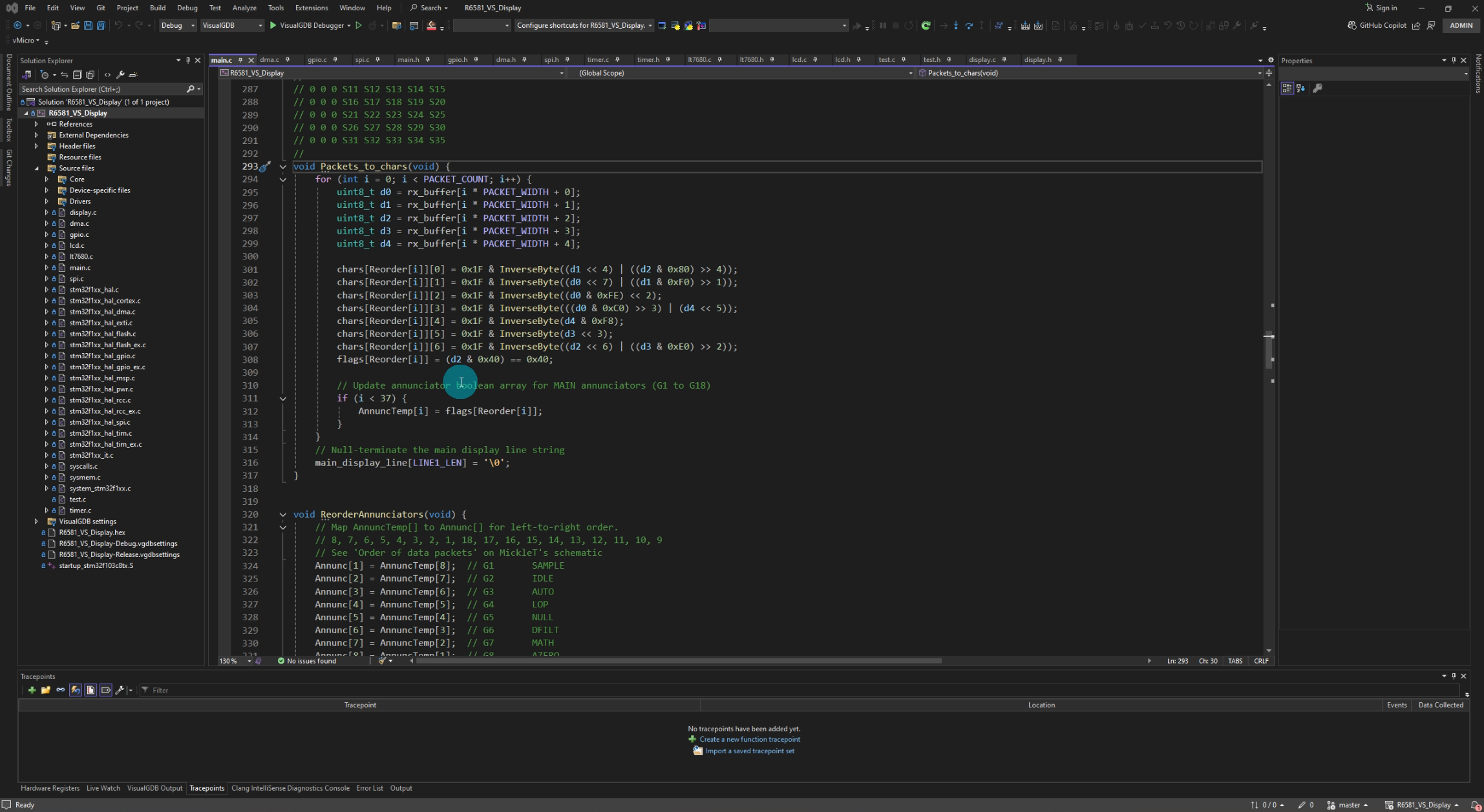
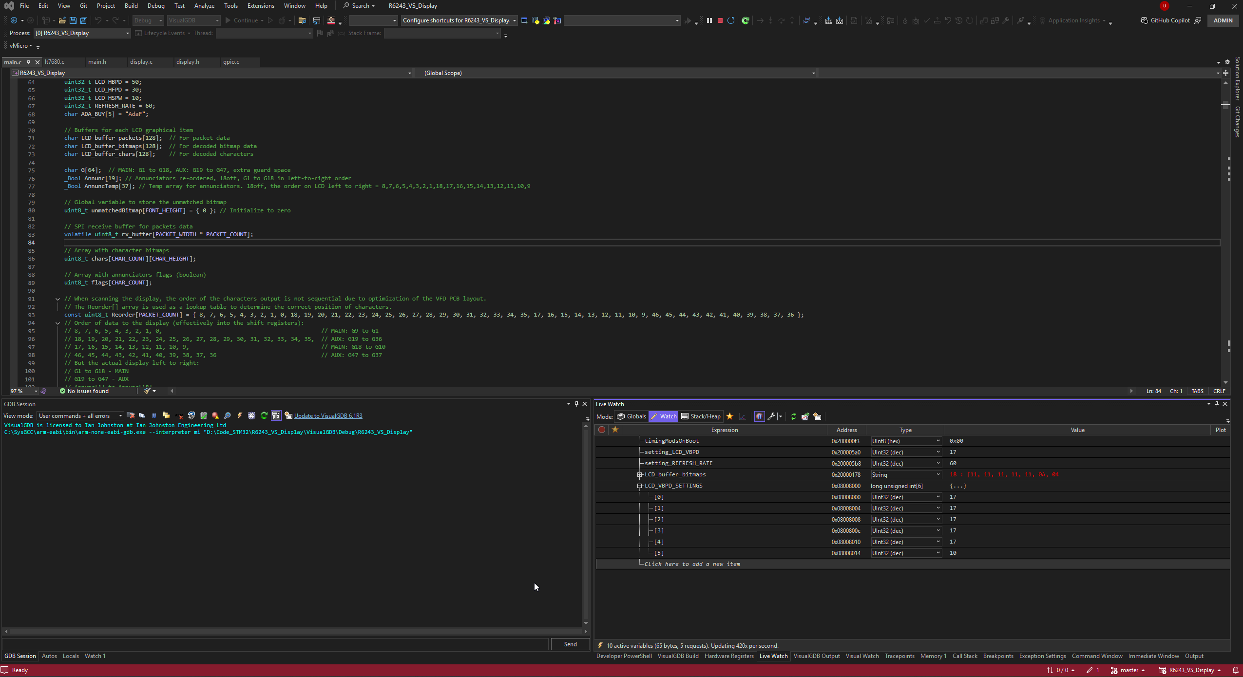
Visual Studio 2022 together with the VisualGDB plugin provides a professional development environment for the firmware.
VisualGDB integrates seamlessly into Visual Studio, allowing embedded STM32 projects to be edited, compiled and debugged without leaving the familiar Visual Studio interface.
It provides full project management, code completion, syntax highlighting, integrated build tools, source-level debugging, and direct programming of the target hardware via an ST-LINK debugger.
The ability to set breakpoints, inspect variables and registers, view memory, and single-step through the firmware greatly simplifies the development and debugging of complex real-time embedded applications.
By combining Microsoft's powerful IDE with the GNU ARM toolchain and STM32 development tools, VisualGDB offers a productive and stable environment for developing, testing and maintaining the TFT conversion firmware.
Source-level debugging is done through the BluePill's SWD connector, the USB connector on the BluePill is not used.
You don't need the development environment unless you want to make changes to the code. For the end user all you need is the compiled HEX file which I supply, and then follow the easy programming procedure below.
Two screenshots opposite, VS2022 and also a VisualGDB debugging active session in VS2022, see the Live Watch variables I've added in the bottom right panel.
My current toolchain:
Visual Studio 2022 Community Edition = free
VisualGDB Custom Edition V6.0R8 = $189 (lifetime) - Note: The cheaper Embedded version at $99 would suffice I think. 30-day free trial available also
STLinkv3set debugger/programmer = $45
The Code
The firmware is written entirely in Embedded C, using the STM32 HAL (Hardware Abstraction Layer) libraries supplied by STMicroelectronics.
Most of my TFT conversion projects use the same group of core source files, with only the instrument-specific decoder and display formatting changing significantly between projects. Each `.c` source file normally has a corresponding `.h` header file containing its function declarations, shared constants, pin definitions and data structures. The following is from my 34401A DMM code as an examnple.
The .c source files contain the actual executable code. This includes the functions responsible for hardware initialization, display decoding, TFT graphics, SPI communications, timers and the main program logic. Each source file is dedicated to a specific task, helping to keep the code organised and manageable.
The corresponding .h header files define the public interface to each module. They contain function prototypes, shared constants, macros, data structures, global variable declarations and hardware definitions that need to be accessed by other parts of the firmware. Rather than duplicating these definitions throughout the project, they are declared once in the header file and included wherever required using the C #include directive.
Creating a new project in Visual Studio 2022 using the VisualGDB plugin and selecting the target STM32 device automatically generates much of the project framework. I added to this my application-specific source files (per below), such as the instrument decoder, LT7680 graphics driver, TFT display routines and other custom modules. The result is a professional project structure that combines STMicroelectronics' proven hardware support libraries with user-written application code.
main.c / main.h
`main.c` is the main entry point for the firmware. It initializes the STM32 system clock, GPIO, SPI, DMA, timers, instrument decoder, TFT panel and LT7680 graphics controller. After initialization, the main loop continuously processes incoming instrument data and updates the main display and annunciators when new information is available. It also contains general diagnostic functions such as the Blue Pill speed test, interrupt callbacks and error handling. `main.h` contains shared pin assignments, project-wide definitions and declarations used by the other modules.
gpio.c / gpio.h
These files configure the STM32’s general-purpose input and output pins. This includes the LT7680 reset output, test LED, instrument display-interface inputs, SPI chip-select signals, LCD setup connections and optional jumper or configuration inputs. Interrupt priorities and external interrupt inputs used to capture the instrument’s serial clock are also configured here.
spi.c / spi.h
These files configure the STM32 hardware SPI interface used to communicate with the LT7680 graphics controller. They define the SPI clock polarity, phase, transfer speed, data width and GPIO pin assignments for clock, MOSI, MISO and chip select. DMA support for SPI transfers may also be configured here.
dma.c / dma.h
The DMA module enables and configures the STM32 Direct Memory Access controller and its interrupts. DMA allows data to be transferred between memory and peripherals with minimal processor involvement, which is useful where high-speed or continuous SPI transfers are required.
timer.c / timer.h
These files provide general timing support. They can configure a hardware timer to generate periodic interrupts and contain functions for changing the timer period while the firmware is running. Timer flags can then be used by the main program to schedule slower background or display-related operations.
decoder_34401a.c / decoder_34401a.h
This is the instrument-specific decoding module for the HP/Agilent 34401A. It captures the front-panel serial data one clock edge at a time, assembles the individual bits into bytes, stores them in a FIFO buffer and identifies the different message, annunciator, control and button frames. The decoded reading, annunciator states, blinking information and update counters are then made available to the rest of the firmware. Equivalent decoder files are used for other instruments.
lcd.c / lcd.h
The LCD module communicates directly with the TFT panel’s ST7701S controller during power-up. It uses a software-generated (bit-banged) 9-bit SPI interface to send the panel manufacturer’s initialization sequence, configure the panel timing and colour format, and bring the LCD out of sleep before enabling the display. Once this initial setup is complete, normal screen updates are handled by the LT7680.
lt7680.c / lt7680.h
This is the low-level graphics-controller driver. It contains the routines used to read and write LT7680 registers, reset and initialize the controller, configure its PLL clocks, display RAM, panel resolution, colour depth, front and back porch timing, active display area and backlight PWM. It also provides the general graphics functions used elsewhere in the project, including setting fonts and colours, positioning the text cursor, drawing text and lines, and waiting for the LT7680 graphics engine to become ready before sending further data.
display.c / display.h
The display module controls what the user actually sees on the TFT. It takes the decoded instrument data and formats it into the main reading, units, decimal points, commas, blinking characters and annunciators. It selects the required font sizes, colours and screen positions before calling the lower-level LT7680 drawing functions. It also contains splash-screen and diagnostic display routines, including the Blue Pill speed indication.
Together, these modules form a reusable firmware framework. The hardware initialization and LT7680 display-control files remain broadly similar between projects, while the decoder and display modules are adapted to suit the communication protocol and visual layout of each individual instrument.
Programming the BluePill Board
Use an STLink V2 or STLink V3 programmer. Clone programmers should also work. Leave the Boot0 & Boot1 headers in their default positions. The following can be carried out with the BluePill installed in the instrument and running (preferred method). If programming the BluePill standalone out of the instrument and off my Pcb then you will need to supply the BluePill with +5V.
Note: The SWD 3.3V connection is not used for powering the BluePill, it is an input to STLink and is used for operating & programming voltage detection.
SWD Connections
The 4-way header on the BluePill is used and another pin marked RESET or R.
Note: The USB connector is not used.
| STLink | BluePill |
|---|---|
| SWDIO | SWIO |
| SWCLK | SWCLK |
| GND | GND |
| 3.3V | 3.3V (VREF) |
| NRST | RESET (R) |
Method 1
- Open STM32 ST-LINK Utility.
- Select Target → Connect.
- Select File → Open File.
- Select the required .hex file.
- Select Target → Program & Verify.
- Click Start.
Method 2
- Open STM32 CubeProgrammer.
- Select ST-LINK.
- Set Port = SWD.
- Click Connect.
- Click Open File.
- Select the required .hex file.
- Click Download.
Method 3 (developer)
- Open VS2022 and load the project.
- Build the Solution
- Right click Solution in Solution Explorer
- Click Program & Start Without Debugging
- Note: Hit F5 to start debugging if req'd
Supported Instrument Conversions
Here's what I have done so far, and the possible future projects coming up next!
I don't just pick instruments randomly, I really have to own one myself and also the protocol and hardware/software display interface has to be known or is somewhat reverse engineerable. Then the fun begins!
| Instrument | Original Display | TFT LCD |
|---|---|---|
| Advantest / ADCMT R6581(T) DMM | VFD | 4.58" IPS |
| HP3457A DMM | LCD | 3.71" IPS |
| Advantest / ADCMT R6243 SMU | VFD | 4.58" IPS |
| HP 3478A (3468A) DMM | LCD | 3.71" IPS |
| HP/AGILENT 34401A DMM | VFD | 3.71" IPS |
| HP / AGILENT / KEYSIGHT 3458A DMM | VFD | Future Project? |
| Keithley 2001 / 2002 DMM | VFD | Future Project? |
Donating
Yes, all my conversions are basically open-source & free. I publish all the source code, gerbers and everything else you need to convert your own test instruments just like mine.
Download it all, order your parts and you can end up with a great looking test instrument once again! Many people have.
How about donating?............YES!, you can PayPal me via this link here.
I have put hundreds of hours into these conversions so every penny is much appreciated.
DISCLAIMER: This is educational only, so if you decide to do the same yourself then you are on your own, I can't be held responsible for any problems/issues/damage/injury that may occur if you decide to follow this and try it yourself.
